Stirley Farm EnerPHit: Timber Frame Walls
Things have been going a bit slower on site recently thanks to the snow and two week break at Christmas. However, the weather up to Christmas was relatively benign and we were able to get on with the building up of the external walls. We’ve had to heighten the masonry wall to accommodate the extra thickness of the roof. We’ve also had to accommodate a new in situ reinforced concrete beam running along both walls at eaves level. This is to help with structural stability of the existing masonry structure and will be connected to the inner timber framing.
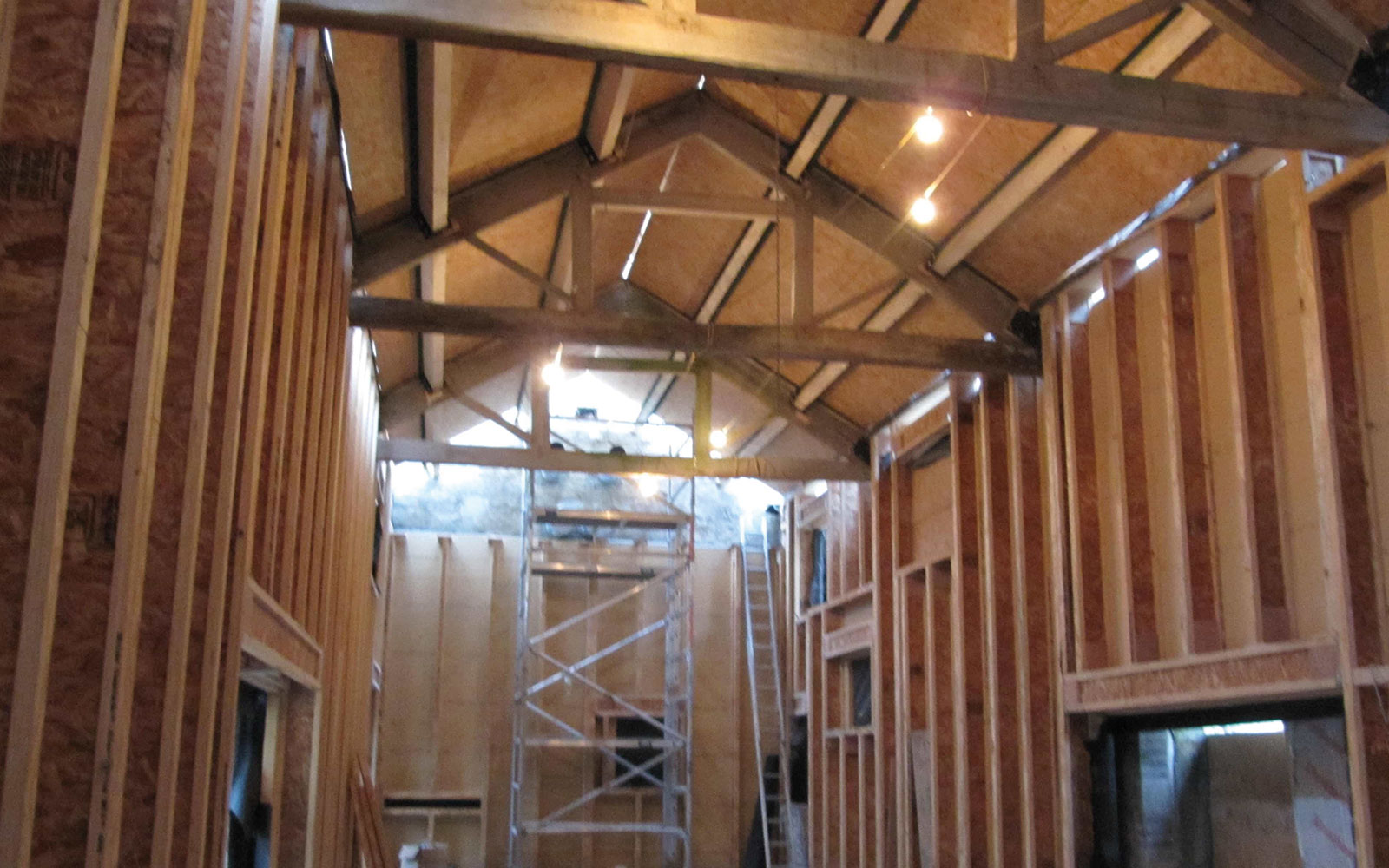
We’ve replaced all the purlins (the timbers between the trusses running horizontally) and we’ve overlaid them with 18mm OSB board (which will eventually act as our airtightness barrier). We have then temporarily laid plastic over that for rain protection. We’ve also made a start on the timber frame walls.
Teplo Ties to replace steel wall connectors
As discussed in a previous blog, a key aspect of our barn conversion will be the use of wall connectors, which will joining the timber frame and masonry walls together (and will help support the masonry wall). This idea has been evolving and we are now exploring the possibility of using adapted Teplo Ties resin anchored into the insitu concrete, instead of the stainless steel threaded bar of our original design to improve our thermal bridging. This is currently being tested for tensile strength, with a plastic threaded bar welded to one end. This will poke through a timber noggin in the inner timber frame wall held fast by a nut and washer of the same material. We’ll include photographs of the wall connectors in future blogs, when we have established exactly which method we are using.
Structural stability – 3-way steel brackets
How to assemble the inner timber I beam wall panels has been a real head scratcher. This system is basically acting as a vertical restraining member to the unstable existing masonry, and has to be tied into the concrete floor slab (straightforward) and tied into the four existing King Post Trusses (complicated!). The horizontal head at the top of the panels is a composite unit made up of two timber I beams with PUR in the web. These are connected to the trusses by a custom made steel bracket thereby utilising the truss to hold the barn together. The wall panels are heavy being 5m high and nominally 2.4m wide and ensuring continuity of wind tightness at the inaccessible rear of the panelling has not been easy.
And of course, the existing walls are not plumb, the trusses are not level and the eaves are not parallel. Our site foreman Jude has done a brilliant job with coping with all these problems. His attention to detail is absolutely fundamental to the success of the project.
The timber frame walls
The timber panels are made up of 241mm TJ timber joists at 600mm centres , which are fabricated on site in 2400mm wide cassettes. On the side facing the masonry wall, we are attaching 60mm Gutex wood fibre sarking board, taped at butt joints for windtightness. On the outside of that (and in a new development from our previous diagram) we have carefully wrapped Pro Clima WA vapour open membrane , also carefully taped at any junctions. We decided to add the WA membrane following discussions with Graham Drummond from Passivhaus Associates, after his visit here in December. Even though we have been reassured about the possibility of moisture entering the timberwork through the masonry walls following the WUFI analysis, we felt that adding the WA membrane would be a ‘belt and braces’ measure. The timber panels are then bolted together and sealed using a bead of Orcon F mastic to ensure wind tightness.
I-beam composite sole plate & header
At the top and bottom of each timber panel or cassette we have developed a TJ joist composite sole plate/ header plate, which comprises two 241mm timber joists for strength, but filled with 50mm of PUR like an insulation sandwich. We didn’t want solid timber as that would have lead to too much of a thermal bridge.
The timber panels themselves will later be filled with mineral wool insulation in a separate operation.
Minimising thermal bridging in the floor to wall junction
Thermal bridging in the floor to wall junction is dealt with by the continuity of insulation under the floor slab continuing around the edge of the slab which then connects to the Gutex wood fibre sarking board and PUR insulation in the I-beam composite sole plate at the bottom of the timber frame. Our External Psi value here is -0.02 W/mK ..
Postscript on ventilated cavity
The WUFI analysis on the project has said that so long as our cavity is ventilated well (eg an air change rate over over 10 ach/ hour) there should be no problem with moisture ingression into the timber frame structure. The only problem is that it seems to be hard to know how to ensure that level of ventilation and so I have just gone with my building experience and put in 40 X 225/75mm plastic air bricks with sleeves through the masonry wall – 20 at ground level and 20 at eaves height – to ensure good air circulation. Each air brick has 7500mm2 free air movement. If anyone has any other suggestions, please let me know!
Bill Butcher, Director, Green Building Store


